
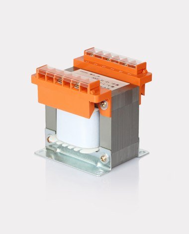
A laminated-core transformer can be the right answer for a robust equipment supply, but the installed result depends on regulation, temperature rise, terminal access and mounting. The useful brief covers all four.
Define the winding schedule
List the primary voltage and taps, each secondary voltage and current, and the permitted output tolerance. Identify simultaneous, alternative and standby operating modes so the design is not based on an impossible combination.
State the load type and power factor or rectifier arrangement where relevant. A winding feeding a capacitor-input rectifier behaves differently from one feeding a resistive load.
Agree the thermal operating point
Provide ambient temperature, enclosure size, mounting orientation and the surfaces available for heat transfer. Distinguish continuous load from short-term overload.
Confirm the insulation class and temperature-rise expectation. A transformer that only works on an open bench may be unsuitable inside the actual panel.
Coordinate the installed package
Define mounting holes, terminal position, lead length, touch protection and cable routing. Confirm the service access needed for testing and replacement.
For export equipment, include the destination standards, label requirements and documentation expected for the approved configuration.